This second installment of the Glenn Murcutt BIM project deals with model manipulation through Revit API and C# computer programming. This project required the modification of the original parametric model from Project #1 for use in the API Revit program. The first step is to install the SDK API packet into the Autodesk Revit program. This will add the external tools and ID selection and specification tools to the Autodesk Revit toolbar. The first step will use the ID selection to get the element number the Autodesk Revit program has specified for the parametric model. Since the parametric model from Project #1 is a Louvered Curtain Panel that is specified and inserted into the Curtain Wall family. Therefore, each one of the individual curtain panels are the same type and can be manipulated the same way and at the same time. The second step in incorporating the API programming into the parametric model is an analysis of the original family model. The second step requires identifying the parameters of the family and determining if they are type or instance parameters. This will affect how the C# programming will obtain the parameters for modification from the Autodesk Revit BIM model. Since we are using several instances of the same Louvered Curtain Panel, we need to manipulate each panel by the same factors. The parameters that we specify and need to alter with the C# programming have to be “type” parameters so the changes will be incorporated to all Louvered Panels in the Model. The parameters that were chosen to be manipulated through the C# programming method are the “Number of Louvers,” “Louver Angle,” and “Sun Altitude Angle.” Each of these parameters will affect the visual appearance of the Louvered Curtain Panel and the performance characteristics of the curtain panel functioning as a shading device. The number of louvers and the angle of the individual louvers determine how much light may enter the house from the north side. Since this project is located in Australia, located below the equator, the north elevation has the most sun exposure. If this project were located in the Northern Hemisphere, the south elevation would have the greatest solar exposure. Therefore, the Louvered Curtain Wall on the north façade of the Glenn Murcutt house will be the greatest deterrent for solar heat gain and too much direct sunlight entering the space.
The program Visual Studio 2008 was used to create the C# programming for manipulating the parametric model. This program uses a graphic interface and code template to generate, build, and debug the C# program. This program works well with the .NET Framework and incorporates traditional Microsoft Windows graphic displays to create programs that work and function well within the Microsoft Windows operating system. For this project, the objective is to create a windows application form that will allow the user to specify new parameter values that then will be applied to the parametric model within the Glenn Murcutt project model. To guide this project, the existing Table-Chair parametric model and C# program tutorial will be used as a reference for this project. This tutorial demonstrates how a windows form application can be designed and programmed to manipulate a parametric model.
By using the Table-Chair C# program as a reference, the “form (design)”, “command.cs”, and “form.cs “ tabs will be changed and adapted for use in this Project #2. The design of the application form was designed using labels, text boxes, and combo boxes to specify or insert new values into the C# program. The previous specified parameters from the louvered curtain panel in the BIM model are specified on the form. The labels specify the each of the type parameters from the Louver Curtain Panel family we are trying to change. The combination of Combo Boxes and Text Boxes allow the user to manually input values for each of the parameters.
The "Command.cs" file contains the C# code that specifies everything for the program. The initial part of the code specifies all the background systems and additional libraries, such as Revit API, that the rest of the program will draw from. Part of this specification, applies several lines of code that determines how the C# programming will react in Autodesk Revit.
using System;
using System.Collections.Generic;
using System.Text;
using System.Windows.Forms;
// Revit libraries
using Autodesk.Revit;
using Autodesk.Revit.DB;
using Autodesk.Revit.UI;
using Autodesk.Revit.DB.Structure;
using Autodesk.Revit.DB.Architecture;
//Excel libraries reference:
//http://www.codeproject.com/KB/office/microsoftexcelclient.aspx
//using ExcelDB;
//CSV libraries source:
//http://commonlibrarynet.codeplex.com/
using ComLib.Entities;
using ComLib.Account;
using ComLib;
using ComLib.CsvParse;
using ComLib.Application;
using ComLib.Logging;
namespace LouverWall
{ [Autodesk.Revit.Attributes.Transaction(Autodesk.Revit.Attributes.TransactionMode.Manual)]
[Autodesk.Revit.Attributes.Regeneration(Autodesk.Revit.Attributes.RegenerationOption.Manual)]
public Autodesk.Revit.UI.Result Execute(ExternalCommandData commandData, ref string message,
ElementSet elements)
{
#region 1. Initialize, get the project, and start a transaction
Result retRes = Result.Failed; // set out default result to failure. Failure will let Revit to undo the changes made during
// the execution of this command.
Document doc = commandData.Application.ActiveUIDocument.Document; // the current Revit project model
Transaction transaction = new Transaction(doc, "Update by API"); //A transaction is a change to the model to be made. The text will show in Revit -> Undo/Redo
transaction.Start(); // Start a transation to allow changes to the model
#endregion
The second part of the programming code specifies the initial elements and initial values of the parametric family parameters. The programming process throughout most of C# programming is simple. First, find and define the element using the ID number from Autodesk Revit. Second, specify the C# programming name. Third, use the ID and newly recognized name, to get the parameters from Autodesk Revit that are going to be changed by the API program.
id = new ElementId(229281);
FamilyInstance louverCurtainPanelInstance = doc.get_Element(id) as FamilyInstance;
#region 3.2. Get Type Parameters of the objects
ElementId typeId = louverCurtainPanelInstance.GetTypeId();
ElementType louverCurtainWall2 = doc.get_Element(typeId) as ElementType;
//Get opening type
//Parameter panelWidthParam = louverCurtainWall2.get_Parameter("Panel Width");
//Parameter panelHieghtParam = louverCurtainWall2.get_Parameter("Panel Hieght");
Parameter louverAngleParam = louverCurtainWall2.get_Parameter("Louver Angle");
Parameter sunAltitudeAngleParam = louverCurtainWall2.get_Parameter("Sun Azimuth");
Parameter numberOfLouversParam = louverCurtainWall2.get_Parameter("#ofLouvers");
//Get the type parameter
#endregion
Most of the C# code follows this specific format of finding variables/elements, specifying there new name for programming purposes, and then telling the program what to "get" from the original model. During this process, the programmer most make sure to use the correct names or ID's in developing the code. For example, when getting a parameter from Autodesk Revit, the name of the parameter must be exactly punctuated and spelled exactly the same as in Autodesk Revit. This is the amount of detail and logic required for C# programming. Some may find this a disadvantage, but others could see this as an advantage because of the specific format. It just depends on the user and their preference.
The next step in the C# programming process identifies the process /equations for calculating values for the parameters. This process is in much of the same format as finding and specifying parameters. First, the program specifies what is being calcualated, the equation for solving for the parametric value, then stating the new value to confirm a correct value. For this particular program, the louver angle parameter and sun altitude angle has to be calculated in radians for the C# program, but then converted back into degrees for Autodesk Revit. This accounts for multiplying the angle values by Pi and then dividing by 180 to get the degree value into radians.
#region 5. Calculate new values
double louverAngleRadian = louverAngle * Math.PI / 180;
MessageBox.Show("Louver Angle: " + louverAngleRadian);
double sunAltitudeAngleRadian = ((90 - louverAngleRadian)*Math.PI)/180;
MessageBox.Show("Sun Altitude Angle: " + sunAltitudeAngleRadian);
#endregion
#region 6. Set parameters of objects using new values
MessageBox.Show("LouverAngle = " + louverAngleRadian);
//Show the updated value
louverAngleParam.Set(louverAngleRadian);
MessageBox.Show("Sun Altitude Angle = " + sunAltitudeAngleRadian);
sunAltitudeAngleParam.Set(sunAltitudeAngleRadian);
#endregion
The last part of the programming process tells the program how to act depending on the result of the processes. If the programming is successful and Autodesk Revit takes the new changes, the program tells the program to save changes and close the solution. If the processes were not a success, the program tells Autodesk Revit to undo all previous changes, and return the model to the original form or value. This completes the C# programming process and covers the basic process of developing a form based code for use in Autodesk Revit.
#region 8. Commit the transaction and terminate the API program
transaction.Commit(); //Let Revit make the change.
// if the program can run to this line, the execution is successful
retRes = Result.Succeeded;
// inform Revit the result (if succeeded, Revit will keep all
// the changes made during the execution of the command).
return retRes;
#endregion
}
}
}
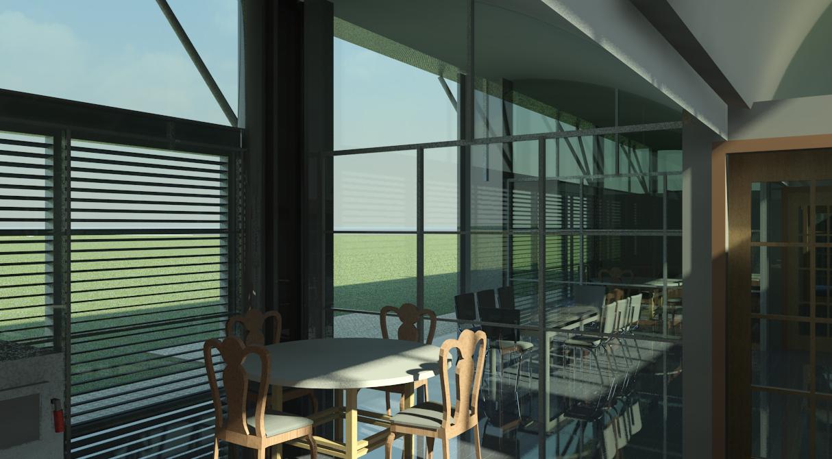
Glenn Murcutt Model without Changes
Glenn Murcutt Model with Changes
Glenn Murcutt Model without Changes
Glenn Murcutt Model with Changes